-
Canon Fax L3000 User Manual Pdf카테고리 없음 2021. 1. 10. 11:40Canon Pixma MX922 printers are the ideal solution for all your printing, copying and enumeration need at home and in the office. Thanks to the flexibility offered by the wireless connection and their elegant and compact design, they can be operated from almost any point of the building. Each printer has a display panel that allows you to effortlessly navigate through the numeric keypad. The Canon PIXMA MX922 has a large screen, which clearly displays menus and images. Canon Pixma All-in-One Desktops are designed to increase efficiency and productivity in home offices. The Pixma MX922 models feature two front loader trays that make it easy to support multiple jobs, allowing two different print media to be loaded and ready at any time. This makes wireless printing much faster and easier since users no longer have to manually load media. For large jobs, the Pixma MX922 models feature a dual automatic charger.

Download drivers, software, firmware and manuals for your Canon product and get access to online technical support resources and troubleshooting. We use cookies to provide you with the best possible experience in your interactions with Canon and on our website – find out more about our use of Cookies and change your cookie settings here.
The Canon Pixma MX922 Multifunction Printer combines all the functions to satisfy your needs as an amateur or professional photographer. It includes 5 replaceable ink cartridges for optimal image quality. It has a 3-inch screen so you can print photos directly from your USB stick or camera (connected via USB cable) and make photocopies without using your computer. Its manual paper feed is designed for standard photo paper sizes, and it also has a tray for printing directly on printable CDs, DVDs, and Bluray. The MX922 also makes it possible to transform the office into a photo lab. Print professional-looking borderless photos up to 21.6 x 28 cm (8.5 x 11 in.). My Image Garden6 software makes it easy and fun to organize and print photos, including Face Detection, Fun Filters, Chronological Organization, Auto Layout Suggestions and more.Service Manual Canon LC800, L1000, L3000 Series;
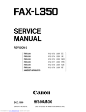
This manual is in the PDF format and have detailed Diagrams, pictures and full procedures to diagnose and repair your Canon.
You can print, zoom or read any diagram, picture or page from this Service Manual. Every chapter on this manual is fully detailed and contain all the simulation codes, trouble codes, maintenance procedures, reset procedures, diagnose procedures of Canon LC800, L1000, L3000 Series. You can find easily everything what do you need.
To see what contain, please read table of contents:Chapter 1. Introduction
1.1 System Construction
1.1.1 System Configuration
1.1.2 System Configuration
1.2 Product Specifications
1.2.1 Names of Parts
1.2.1.1 External View (Front)
1.2.1.2 External View (Rear)
1.2.1.3 Cross-Section
1.2.2 Using the Machine
1.2.2.1 Turning On the Power Switch
1.2.2.2 When Turning Off the Main Power Switch
1.2.2.3 Control Panel
1.2.2.4 Control Panel
1.2.3 User Mode Items
1.2.3.1 PAPER SETTINGS
1.2.3.2 VOLUME CONTROL
1.2.3.3 COMMON SETTINGS
1.2.3.4 COPY SETTINGS
1.2.3.5 TX/RX SETTINGS
1.2.3.6 ADDRESS BOOK SET
1.2.3.7 PRINTER SETTINGS (If an network printer kit is attached.)
1.2.3.8 TIMER SETTINGS
1.2.3.9 ADJUST./CLEANING
1.2.3.10 REPORT SETTINGS
1.2.3.11 SYSTEM SETTINGS
1.2.4 Maintenance by the User
1.2.4.1 User Maintenance Items
1.2.4.2 Cleaning
1.2.5 Safety
1.2.5.1 Safety of Toner
1.2.5.2 Safety of the Laser Light
1.2.5.3 CDRH Regulations
1.2.5.4 Handling the Laser Unit
1.2.5.5 Point to Note about Fire
1.2.5.6 Cautions as to the replacement and disposal of lithium battery
1.2.5.7 Storing and Handling the Cartridge Before Unpacking
1.2.5.8 Storing or Handling the Cartridge After Unpacking
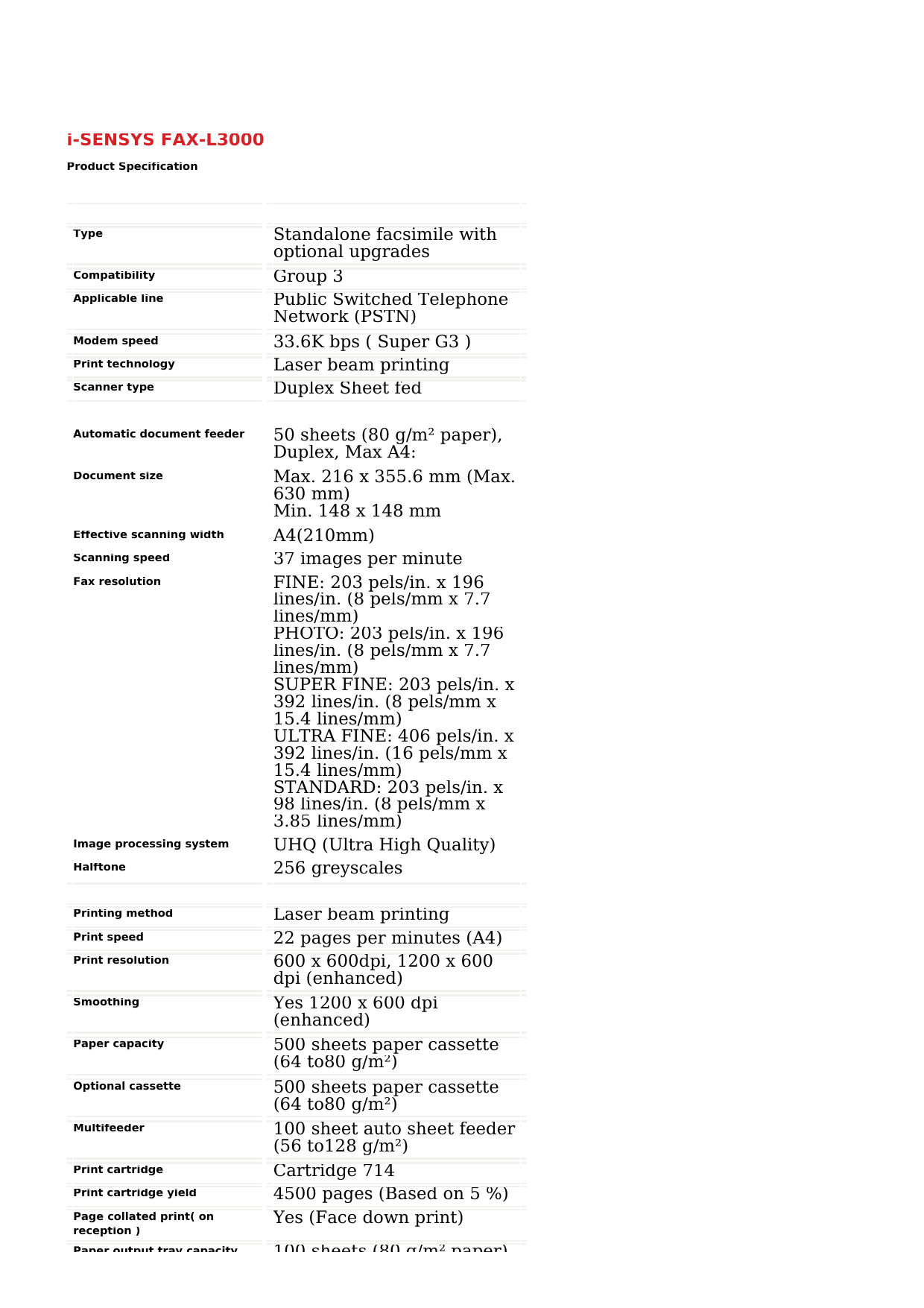
1.2.6 Product Specifications
1.2.6.1 Product Specifications
1.2.6.2 Product Specifications
1.2.6.3 ADF Specifications
1.2.6.4 ADF Specifications
1.2.6.5 Fax Specifications
1.2.7 Function List
1.2.7.1 Printing Speed
1.2.7.2 Types of PaperChapter 2. Installation
2.1 Making Pre-Checks
2.1.1 Selecting the Site of Installation
2.1.2 Before Starting the Work
2.1.3 Checking the Contents
2.2 Unpacking and Installation
2.2.1 Unpacking and Removing the Packaging Materials
2.2.2 Installing the Toner Cartridge
2.2.3 Setting the Paper
2.2.4 Connecting the Cable
2.2.5 Connecting the Cable
2.2.6 Checking the Image Quality
2.2.7 Setting the Date and Time
2.2.8 Checking the Network Connection
2.2.9 Connecting to the Telephone Line
2.3 Installing the Hand Set
2.3.1 Checking the Contents
2.3.2 Installing the Hand Set
2.4 Installing the Stamp Unit
2.4.1 Checking the Contents
2.4.2 Installing to the Host Machine
2.4.3 Checking the OperationChapter 3. Basic Operation
3.1 Construction
3.1.1 Functional Construction
3.1.2 Functional Block Diagram
3.1.3 Image Processor PCB
3.1.4 DC Controller PCB
3.1.5 Reader Controller PCB
3.1.6 Power Supply PCB
3.1.7 NCU PCB
3.1.8 Modular Jack PCB
3.1.9 Modem PCB
3.2 Basic Sequence
3.2.1 Basic SequenceChapter 4. Original Exposure System
4.1 Basic Constraction
4.1.1 Specifications, Control Methods, and Functions
4.1.2 Specifications, Control Methods, and Functions
4.1.3 Major Components
4.1.4 Major Components
4.2 Basic Sequence
4.2.1 Basic Sequence at Power-on
4.2.2 Basic Sequence after Depression of Start Key (One Sheet of Original)
4.3 Various Control
4.3.1 Enlargement/Reduction
4.3.1.1 Magnification Change in Vertical Scan Direction
4.3.1.2 Magnification Change in Horizontal Scan Direction
4.3.2 Dirt Sensor Control
4.3.2.1 Outline
4.4 Parts Replacement Procedure
4.4.1 Copyboard Glass
4.4.1.1 Removing the Stream Reading Glass
4.4.1.2 Removing the Stream Reading Glass
4.4.1.3 Action after Replacing the Stream Reading Glass (if equipped with the SEND Functions)
4.4.2 Reader Controller PCB
4.4.2.1 Removing the Reader Controller PCB
4.4.3 Contact Sensor
4.4.3.1 Removing the Contact Image Sensor
4.4.3.2 Removing the Contact Image Sensor
4.4.3.3 Action after Replacing the Contact Image Sensor
4.4.4 Contact Sensor HP Sensor
4.4.4.1 Removing the Contact Image Sensor Unit HP SensorChapter 5. Original Feeding System
5.1 Basic Constraction
5.1.1 Overview
5.1.2 Drive Mechanism
5.2 Basic Operation
5.2.1 Outline of Operation Mode
5.2.2 Document Size Detection
5.2.3 Document Size Detection
5.2.4 Paper Pickup Operation
5.2.5 Reversal Operation
5.2.6 Delivery Operation
5.3 Detection Jams
5.3.1 Overview
5.4 ADF
5.4.1 Pick-up/Feed Roller Unit
5.4.1.1 Pickup/Feed Roller Unit
5.4.2 Pick-up Roller
5.4.2.1 Removing the Pickup Roller
5.4.3 Feed Roller
5.4.3.1 Removing the Feed Roller
5.4.4 Pick-up Motor
5.4.4.1 Removing the ADF Pickup Motor
5.4.5 Read Motor
5.4.5.1 Removing the Read Motor
5.4.6 Document Set Sensor
5.4.6.1 Removing the Document Set Sensor
5.4.7 Document Length Sensor
5.4.7.1 Removing the Document Length Sensor 1/2
5.4.8 Document width sensor
5.4.8.1 Document Width Sensor
5.4.9 Document Edge Sensor
5.4.9.1 Removing the Document Edge Sensor
5.4.10 Registration Sensor
5.4.10.1 Removing the Registration Sensor
5.4.11 Separation Sensor
5.4.11.1 Removing the Separation Rear Sensor
5.4.12 Delivery Sensor
5.4.12.1 Removing the Delivery Sensor
5.4.13 Release Solenoid
5.4.13.1 Removing the Roller Release Solenoid
5.4.14 Shading Clutch
5.4.14.1 Removing the Shading Clutch
5.4.15 Pick-up Clutch
5.4.15.1 Removing the Pickup Clutch
5.4.16 Separation Pad
5.4.16.1 Removing the Separation PadUser manual for amiccom smart ip camera. Chapter 6. Laser Exposure
6.1 Overview/Configuration
Contents
6.1.1 Specifications and Control Mechanism
6.1.2 Main Components
6.2 Parts Replacement Procedure
6.2.1 Laser/Scanner Unit
6.2.1.1 Removing the Laser Scanner UnitChapter 7. Image Formation
7.1 Overview/Configuration
7.1.1 Specifications and Control Mechanism
7.1.2 Outline
7.2 Image Formation Process
7.2.1 Cross-Section (Main body)
7.3 Parts Replacement Procedure
7.3.1 Transfer Charging Roller
7.3.1.1 Removing the Transfer Charging RollerChapter 8. Pickup and Feed System
8.1 Overview/Configuration
8.1.1 Outline
8.2 Detection Jams
8.2.1 Jam Detection Outline
8.2.1.1 Outline
8.2.1.2 Types of Jams
8.3 Cassette Pickup Unit
8.3.1 Outline
8.3.2 Retry Pickup
8.3.3 Detecting the Size of Paper
8.4 Duplex Unit
8.4.1 Outline
8.5 Manual Feed Pickup Unit
8.5.1 Outline
8.5.2 Retry Pickup
8.5.3 Detecting the Size of Paper
8.6 Parts Replacement Procedure
8.6.1 Cassette Pickup Roller
8.6.1.1 Removing the Cassette Pickup Roller
8.6.2 Cassette Separation Roller
8.6.2.1 Removing the Cassette Separation Roller
8.6.3 Cassette Paper Sensor
8.6.3.1 Removing the Cassette Paper Sensor
8.6.4 Cassette Pickup Solenoid
8.6.4.1 Removing the Cassette Pickup Solenoid
8.6.5 Paper Feed Roller
8.6.5.1 Removing the Cassete Feed Roller
8.6.6 Manual Pickup Roller
8.6.6.1 Removing the Manual Pickup Roller
8.6.7 Manual Feed Tray Paper Sensor
8.6.7.1 Removing the Manual Tray Sensor
8.6.8 Manual Pickup Solenoid
8.6.8.1 Removing the Manual Pickup Solenoid
8.6.9 Manual Separation Roller
8.6.9.1 Removing the Manual Separation Pad
8.6.10 Registration Roller
8.6.10.1 Removing the Registration Roller
8.6.11 Registration Sensor
8.6.11.1 Removing the Registration Sensor
8.6.12 Duplex Pick-up Solenoid
8.6.12.1 Removing the Duplex Pickup Solenoid
8.6.13 Registration Clutch
8.6.13.1 Removing the Registration Clutch
8.6.14 Main Motor
8.6.14.1 Removing the Main MotorChapter 9. Fixing System
9.1 Overview/Configuration
9.1.1 Specifications, Control Mechanisms, and Functions
9.1.2 Outline
9.2 Various Control Mechanisms
9.2.1 Controlling the Temperature of the Fixing Unit
9.2.1.1 Outline
9.2.2 Controlling the Fixing Film Temperature
9.2.2.1 Controlling the Fixing Film Temperature
9.2.2.2 Target Temperatures by Mode
9.3 Protection Function
9.3.1 Outline
9.3.2 Failure Detection
9.4 Parts Replacement Procedure
9.4.1 Fixing Unit
9.4.1.1 Removing the Fixing Unit
9.4.1.2 Installing the fixing unit
9.4.2 Fixing Film Unit
9.4.2.1 Removing the Fixing Film Unit
9.4.3 Fixing Pressure Roller
9.4.3.1 Removing the Pressure Roller
9.4.4 Fixing Delivery Paper Sensor
9.4.4.1 Removing the Delivery Sensor
9.4.5 Delivery Full Sensor
9.4.5.1 Removing the Delivery Full SensorLittle Dot Mk3 Manual Also is enywhere the actual output impedance of little dot mk3? Thanks a lot!!!!! From this Here is a link to the Little Dot manual for MKIII. Pages 8 and 9 have. 5 Little Dot MK III Introduction Thank you for purchasing the Little Dot MK III vacuum tube headphone amplifier! Hope this manual can help you easily enjoy your. Little dot mk iii manual pdf. The Little Dot MK III also adds in user-tweaking options such as two gain 6.3 mm gold-plated adapter. 1 User's manual. 1, This product is located in German. 5 Little Dot MK III Introduction Thank you for purchasing the Little Dot MK III vacuum tube headphone amplifier! Hope this manual can help you easily enjoy your. Little Dot MK III The I+ from Little Dot is an excellent tube hybrid that offers much more than its sub-$150 price tag would suggest. This is the first piece of User Manual: Contains instructions to operate the 1+ and other warranty. Little Dot Mk Iii Owners Manual The Little Dot MKIII is an imported Chinese-made tube amp with both pre- and power-amp Here's an extract from the manual regarding use as a pre-amp. I got my LD MK III in a few days after ordering it, but that was to the US. Other than the 8 hours - 1 hour on-off instruction on the LD i+ manual. Stereo Headphones SERVICE MANUAL. Output on my amp, sounds incredible Little Dot MK III, Bottlehead Crack. To buy Crack Manual Version 52810 A guide to constructing the Crack Output. Little Dot DACI is an exceptionally versatile, reference-quality external DAC unit Little Dot MK III Headphone Tube Amplifier & PreAmp & tube AMPLIFIER.
Fairywill sonic electric toothbrush black users manual. Sep 10, 2019 ultra sonic ultra powerful electric toothbrush powered toothbrush electric tooth brush Color: white Sku#320 This electric toothbrush is with professional design and advanced sonic cleaning technology, taking care of your dental health by high-quality brushing, removing plaque better than a general manual toothbrush, keeping your teeth cleaner, stronger and gum.
Contact Customer Service using the link on, or call 1-800-323-9601. We have assembled these electronic versions of our current and past owner’s manuals for your convenience. The total gun manual download.
As with the rest of the 140RC Series alarm the Ei146RC Optical alarm can be interconnected with other alarms and accessories through hard wire connection or, for less mess and disruption, by wireless interconnection.As this alarm contains a 9V Alkaline battery back up, this battery will need changing over the course of it’s ten year life. By fitting an Optical alarm in these areas you are less likely to get nuisance alarms, especially if the alarm is located close to the Kitchen.The alarm is supplied with an to make it as quick and simple to install. https://piecongetis.tistory.com/5. By fitting an Optical alarm in these areas you are less likely to get nuisance alarms, especially if the alarm is located close to the Kitchen.The alarm is supplied with an to make it as quick and simple to install. Click here for our. As with the rest of the 140RC Series alarm the Ei146RC Optical alarm can be interconnected with other alarms and accessories through hard wire connection or, for less mess and disruption, by wireless interconnection.As this alarm contains a 9V Alkaline battery back up, this battery will need changing over the course of it’s ten year life.
Canon User Manuals Pdf
Chapter 10. External and Controls
10.1 Control Panel
10.1.1 Outline
10.2 Fan
10.2.1 Outline
10.3 Power Supply
10.3.1 Power Supply
10.3.1.1 Outline
10.3.1.2 Rated Output of the Power Supply PCB
10.3.2 Protection Function
10.3.2.1 Protective Functions
10.4 Parts Replacement Procedure
10.4.1 External Cover
10.4.1.1 Exteranal Covers
10.4.1.2 Removing the Rear Cover
10.4.1.3 Removing the Left Middle Cover
10.4.1.4 Removing the Left Front Cover
10.4.1.5 Removing the Left Rear Cover
10.4.1.6 Removing the tray Lower Cover
10.4.1.7 Removing the Right Cover
10.4.1.8 Removing the Front Cover
10.4.1.9 Removing the Document Feeder Tray
10.4.1.10 Removing the Document Delivery Tray
10.4.1.11 Removing the Delivery Tray
10.4.2 Main Drive Unit
10.4.2.1 Removing the Main Drive Unit
10.4.3 Pick-up Drive Unit
10.4.3.1 Removing the Pickup Drive Unit
10.4.4 Fixing/Duplex Drive Unit
10.4.4.1 Removing the Fixing/Duplex Drive Unit
10.4.5 Operation Panel Unit
10.4.5.1 Removing the Operation Panel Unit
10.4.6 Image Processor PCB
10.4.6.1 Before Installation (Backup of Data)
10.4.6.2 Removing the Image Processor PCB
10.4.6.3 Procedure after Replacing the Image Processor PCB
10.4.7 RAM
10.4.7.1 Removing the SDRAM
10.4.8 DC Controller PCB
10.4.8.1 Removing the DC Controller PCB
10.4.9 Powwer Supply PCB
10.4.9.1 Removing the Power Supply PCB
10.4.10 Relay PCB
10.4.10.1 Removing the Relay PCB
10.4.11 NCU PCB
10.4.11.1 Removing the NCU PCB
10.4.12 Modem PCB
10.4.12.1 Removing the Modem PCB
10.4.13 Modular Jack PCB
10.4.13.1 Removing the Modular Jack PCB
10.4.14 Filter PCB
10.4.14.1 Removing the Filter PCB (230V model only)
10.4.15 Network PCB
10.4.15.1 Removing the Network PCB (if equipped with the network functions)
10.4.16 Send PCB
10.4.16.1 Removing the SEND PCB (if equipped with SEND functions)
10.4.17 Capacitor PCB
10.4.17.1 Removing the capacitor PCB
10.4.18 Interlock Switch
10.4.18.1 Removing the Interlock Switch
10.4.19 Fan
10.4.19.1 Removing the Heat Discharge Fan
10.4.19.2 Removing the Reader Fan
10.4.20 Speaker
10.4.20.1 Removing the Speaker

Chapter 11. RDS
11.1 RDS
11.1.1 Overview
11.1.2 Application Operation Mode
11.1.3 Communication Test
11.1.4 Communication Log
11.1.5 Detail of Communication Log
11.1.6 Initialization of e-RDS
11.1.7 SOAP Communication Function
11.1.8 Retransmission at the time of SOAP Transmission Error
11.1.9 e-RDS Setting Screen
11.1.10 Report Output of Communication Error Log
11.1.11 Sleep Operation
11.1.12 Alarm Filtering, Alert Filtering
11.1.13 CA Certificate
11.1.14 Settings of Network Connection (Installation/Maintenance)
11.1.15 Settings of e-RDS (Installation/Maintenance)
11.1.16 Troubleshooting
11.1.17 Error Message listChapter 12. Maintenance and Inspection
12.1 Periodically Replaced Parts
12.1.1 Periodically Replaced Parts
12.2 Consumables
12.2.1 Durables
12.3 Periodical Service
12.3.1 Periodeical Service ItemsChapter 13. Measurement and Adjustments
13.1 Image Adjustments
13.1.1 Image parallelism adjustment
13.2 Scanning System
13.2.1 Action after Replacing the Contact Image Sensor
13.3 Electrical Adjustments
13.3.1 Procedure after Replacing the Image Processor PCB
13.3.2 Actions to Take before All Clearing (Backing up the User Data)
13.4 ADF
13.4.1 Outline
13.4.1.1 Outline
13.4.1.2 Preparing a Test Sheet for Adjustment
13.4.2 Adjusting the Electrical System
13.4.2.1 Adjusting the Magnification
13.4.2.2 Adjusting the Horizontal Registration
13.4.2.3 Adjusting the Horizontal Registration
13.4.2.4 Leading edge registration adjustmentChapter 14. Correcting Faulty Images
14.1 Initial Checkup
14.1.1 Site Environment
14.1.2 Checking the Paper
14.1.3 Checking the Placement of Paper
14.1.4 Checking the Durables
14.1.5 Checking the Units and Functional Systems
14.1.6 Others
14.2 Outline of Electrical Components
14.2.1 Clutch/Solenoid/Motor/Fan
14.2.1.1 List of Clutches/Solenoids/Motors/Fans
14.2.2 Sensor
14.2.2.1 List of Sensors
14.2.3 PCBs
14.2.3.1 List of PCBs
14.2.4 Others
14.2.4.1 List of Lamps, Heaters, and OthersChapter 15. Error Code
15.1 Error Code
15.1.1 List of Error Codes
15.2 Jam Code
15.2.1 Jam Codes (Main body)
15.2.2 Jam Codes (ADF)
15.3 Fax Error Codes
15.3.1 Outline
15.3.1.1 Error Code Outline
15.3.2 User Error Code
15.3.2.1 User Error Code
15.3.3 Service Error Code
15.3.3.1 Service Error CodeCanon Fax L3000 User Manual Pdf Online
Chapter 16. Service Mode
Chapter 17. Upgrading
17.1 Outline
17.1.1 Overview of Upgrade
17.1.2 Overview of Service Support Tool
17.2 Making Preparations
17.2.1 Connection
17.2.2 Registering the System Software
17.3 Downloading System Software
17.3.1 Downloading the System Software
17.3.1.1 Downloading Procedure
17.3.2 Downloading the Boot Software
17.3.2.1 Downloading Procedure
17.3.3 Otehr Upgrade Methods
17.3.3.1 Downloading the SEND SoftwareChapter 18. Service Tools
18.1 Service Tools
18.1.1 Special ToolsNumber of pages: 324.